I can't believe October came and went so quickly! (It's way too easy to get sidetracked.) Anyway, I just received some new Dental plaster and some additives to try out so now I have no more excuses. Time to roll up my sleeves and start testing. Hopefully it won't take a month this time to show some progress.
Thanks for being patient.
Thursday, November 5, 2009
Sunday, October 4, 2009
I could use a thousand words or.....
 I was asked to describe how the various components interact. Instead of a lengthy (and confusing) description I offer these diagrams and a (hopefully) shorter description. The first step to building a 3DP is to modify the inkjet into a flatbed printer. To that end you need to have a way to move the entire printer over the paper instead of the paper under the printer. There are 2 problems with moving the printer body directly with the original paper feed motor. First, it probably isn't strong enough and second it will probably make unwanted movements as the printer tries to ready a new piece of paper. My solution was to place a homemade encoder on the paper feed motor that would supply "step" pulses to a second more powerful stepper motor. In this way I could easily interrupt the pulses and stop the gantry movement even if the paper feed motor was still moving. Another source of pulses can be used to return the gantry to the starting position. Switches 1 and 3 are "safety" limit switches to prevent over travel of the gantry. Switch 2 swaps the source of the pulses and changes the printer from "print" to "reset". Also, you will need some way to tell the printer when the "paper" is present and "out". Usually there is an optical sensor which you can block/unblock at the appropriate times. This setup works if you are printing only one page at a time and don't mind resetting it manually each page. Of course, you could design a circuit to automate the switching process and replace switch 2 with a relay.
To make a 3DP I needed to not only automate the "reset" but also, precisely control the movement of 2 bins, switch a dc motor on an off, and be able to tell the printing computer to "wait" and not send the next page until the printer is ready. I could have built a dedicated circuit to do all this but as I stated earlier, My knowledge of electronics is limited and I don't have a clue how to program a PIC. I decided instead to go with a CNC setup. The inkjet still does all the actual printing then the CNC takes over and re setts the gantry, adjusts the powder bins,spreads the powder, and then tells the printing computer that it can send the next page. You can see in the diagram that PC 2 has replaced the pulse generator and a relay has replaced switch 2. Additionally, 2 more steppers and a 2 axis stepper driver have been added. Switch 4 gives feedback to the control program and signals the change from the print to the recharge cycle. Relay 2 breaks the connection on pin #11 of the inkjet's parallel port. this tells the PC that the printer is "busy" so it wont send another page until the printer is ready. Relay 3 is connected to the motor that runs the powder roller. The breakout board is a convenient place to make all the connections to the parallel cable and PC 2. Note that the parallel port of the PC doesn't output enough current to drive a relay directly so I used the outputs to switch transistors that supply 5v to the relays.
For the CNC control I use TurboCNC and a G-code program. The program is a step by step set of instructions which can be used to set the logic state (high/low) of the parallel port pins. Also, pins can be monitored and step pulses can be sent to the stepper drivers.
Hopefully this helps clarify what I've done. If I haven't answered your questions feel free to ask.
Wednesday, September 23, 2009
Time to get back to it.
Well, I’ve allowed myself to be distracted the last few weeks but now it’s time to get back to it. Now I’m at the testing phase and my motivation has waned terribly. I guess I was not looking forward to repetitive tests to find the best powder/ink formulations. But, now it’s time to get off my lazy butt and, as the old Nike ad once said, “Just do it”. Anyway, in an effort to self-motivate I’ve been creating a CAD model for the first project to be printed. Now I just need to finish the testing so I can get to it.
 Here is a shot of the project I mentioned. It’s a tabletop holder for one of those LED tea lights. The top and bottom halves are separate. Total height is about 7 inches (18 cm). Each piece will be approximately 900 layers! I reeeeeally need to make sure the printer is working flawlessly before I attempt it.
When I mention this project to my friends, most are like “That sounds really cool, but what are you going to do with it?” The answer depends a lot on the properties of the “printed” plaster. The level of detail and the hardness of the “prints” will determine what I can (or can't) do with them. What I hope to be able to do is model on the computer then “print” parts which can be used as masters to make molds for urethane casting. Well, that’s the goal anyway. I’ll have to see what it can do and modify my expectation accordingly.
 Here is a shot of the project I mentioned. It’s a tabletop holder for one of those LED tea lights. The top and bottom halves are separate. Total height is about 7 inches (18 cm). Each piece will be approximately 900 layers! I reeeeeally need to make sure the printer is working flawlessly before I attempt it.
For now, I’ll busy myself with some small geometric shapes as I test/tweak the equipment. Of course I’ll let you know how it goes.
Wednesday, September 9, 2009
“It cuts though a tin can then slices a tomato!”
While I’m waiting to make repairs/ improvements to the belts, I thought I might take a moment to talk about slicing stl files. I did some Google searches and found several software packages that could slice my files but they were way out of my price range. I guess if I was going into business as a rapid prototyper I could rationalize the expense, but for my own personal/hobby use the prices were prohibitive. There were some budget (free) options (like slicing with PovRay) but I couldn't get them to work and didn’t understand the scripting involved. Then I found the Project 1 utility at the Yahoo DIY 3D Printing and Fabrication group. Thank you Paulo, for graciously making your slicer available to the groups’ members.
The utility is easy to use and doesn’t require any additional programming skills. Simply open your stl file in the slicer, pick a printer, set the slice thickness, and hit print. You can scale and rotate the model as well as shift the print position to center it on the page. One thing to note is that the measurements are in metric. You need to convert your stl to millimeters if you want it to print at the size you are expecting. My other observation is that the mesh must be clean and watertight. From what I understand, that’s not unusual for 3D printing. It’s probably also the reason the other software was so expensive. Unfortunately, my meshes are typically neither clean nor watertight (I really need to learn better 3D modeling skills).
I am modeling in Silo and using MeshLab to check and repair my meshes. Some are so hopelessly messed up that I’ll have to go back and start over. (There is also a slice feature in MeshLab but it outputs svg outlines and I need silhouettes.) MeshLab is open source and can be found at Sourceforge (http://sourceforge.net/projects/meshlab/). Silo is available from Nevercenter (http://www.nevercenter.com/about/) for a modest $99 ($159 for the pro version). They have a 30 day trial if you want to check it out and a very friendly and helpful users community. I'm still very much a Noob with Silo but I found it to be much more intuitive than Blender and WAY less expensive than Rhino, Lightwave, or any of the CAD packages (Hell, even Google Sketch Up is like $495 if you want to be able to output anything other than their own format). Again, if this wasn't a hobby (and I wasn't incorrigibly cheap), expese wouldn't be such a big issue.
Anyway, now I need to make my repairs and whip up some test files.
Monday, September 7, 2009
Lather, Rinse, Repeat
 Well I filled it with powder and took it for a test drive. The first thing I noticed was that I needed to add something to keep the powder from spilling over the sides of the bins as it was being rolled out. I'm still tinkering with the roller speed trying to get the smoothest layer possible. (I think the problem may be partly with my plaster formula) Anyway it was good enough to run some tests.
The print and recharge cycles run great. (Sorry for the really awful video) I am using Paulo Cesar's Project 1 (available at the Yahoo DIY 3D Printing and Fabrication group) to slice my stl files. Many thanks to Paulo for a slicer utility that is easy to use and doesn't require me to know how to script or program.
Oh Noooo!!!!! Somewhere around layer 170 one of the belts came loose! I'm going to have to come up with a more secure clamp. Once I get the belts fixed I'll be ready to try again. For now I'm trying to use up the ink in a new cartridge. I tried to refill an old one with the water/vodka mix but it was hopelessly clogged. I figure I'll have better luck with a new one. For now I'll keep working on getting the powder layer as smooth as possible. I also need to install a limit switch on the supply bin so it stops when it reaches the top.
Thursday, September 3, 2009
Some Assembly Required
Putting it all together:


I had an old cabinet (scavenged of course from an office renovation), that makes the perfect home for my new printer. I screwed the MDF board, with the rails and inkjet, to the top of the cabinet and attached all the electrical bits to the side (I'll move them inside once I'm satisfied it all works). I carefully cut a hole in the MDF under the printer and lowered the bins into place. I used shims to level it at the right height before I screwed it to the inside of the cabinet. I also used some angle braces to support the bottom edge of the bins. I next installed the steppers and lead screws. Luckily there was just enough room between the screws for the PC. I also rigged up a plastic storage container to catch the powder overflow. I mounted the keyboard in the space where a drawer once was. Lastly, I put a shelf above the printer so I would have someplace to put the monitor, my laptop and the mouse. If I were to put the plastic covers back on the inkjet it might even look semi-professional.


Welcome to The Pit of Despair!
 As I mentioned earlier, my build chamber will be 8 ½ x 11 x 10 inches. The supply bin will be half that size. There will also be a small chute (henceforth known as “The Pit of Despair”) so excess powder can be collected . I chose to construct the bins out of some 12 inch wide melamine shelving which I salvaged. I hate cutting large pieces on the table saw and these were already the right width. I only had to cut them to length which made it much easier to keep them “square”. Also, they don't need painting or sealing. I had a problem with the clearance on one side of the printer. The printing area started about ¼ inch from the cartridge cleaning/parking station. I solved this by topping that side with a piece of aluminum angle.
 For the platforms I used more of the melamine shelving. I edged the platforms with felt weatherstrip. This seems to slide nicely on the melamine and should give me a good enough seal. I might have some leakage at the corners but if it's a problem I can always remove the platform and vacuum it out. I used roller skate bearings on the build platform and where the poles exit the bins. I used Teflon sliders on the supply bin because they were cheap and I don't need the same precision on the supply side. The pole is a piece of galvanized conduit which I attached with some pipe fittings and set screws.
 The lead screws and nuts I removed from automotive jacks. I figured if they could lift a car they would be more than sturdy enough. A trip to the junkyard netted me 2 jacks for $5. What a deal! (It did take me a couple hours with a hacksaw to remove the screws and nuts so maybe it wasn't that great a deal) A while back I picked up 2 surplus steppers with gearboxes from www.allelectronics.com. They were like $15 each and I couldn't pass them up. I'm glad I didn't because they are perfect for this project. The gear ratio is 18:1 so there is plenty of torque to lift the heavy bins full of plaster. It took a little Macgyvering to attach the screws to the gearboxes.
Now that the bins are complete, they need to be installed under the printer.
“Control, This is Max.”
All right, so I’ve got it to move in one direction while it prints. Now I need it to go back to where it started, while at the same time;
- Taking control of the belt drive stepper (from now on the X axis)
- Telling the computer (my laptop) that the printer is busy
- Telling the printer a new piece of paper has been fed
- Starting the powder roller motor
- Raising the supply bin
- Lowering the build bin
- Moving the roller across the bins (to spread the powder)
- Stopping the powder roller motor
- Giving the printer back control of the X axis
- Telling the computer (my laptop) that the printer is ready for the next page
- Then it needs to wait while the printer does its thing and repeat at the appropriate time, as many times as necessary.
 To that end I’m using a 3 axis CNC setup to run the show. Without going into a full explanation of CNC, I’ll just say that the software allows you to use the computers parallel port to send the step and direction signals to the stepper drivers. It also allows several configurable outputs and inputs that can be used to activate relays and transistors or to monitor switches and sensors. A relatively simple list of commands (g-code) tells the software what to do.
 - I use one of the outputs to switch the step input to the X axis from the encoder to the computer. This puts the computer in control of the X axis. I used some switching transistors but probably could have used a simple SPDT relay.
- Another of the outputs is used to activate a relay that breaks the circuit on pin #11 of the parallel port of the inkjet printer. (I don’t know how this is done on a USB connection) This tells the printing computer (my laptop) that the printer is busy so it won’t try to print.
- I had used yet another output to supply power to an opto-interrupter that I placed over top of the paper sensor on the printer. The idea was that by turning the sensor on and off, I could simulate a paper present/not present state. It worked, for a while, but stopped when the sensor apparently burned out. Now I have a “flag” on a small rod that the printer literally backs into as it reaches the end of the page, telling it that the paper is out. As the axis moves forward again it pulls away from the flag and thinks the next page has been loaded.
- I use the “spindle on” output to trip a relay and power the powder roller.
- The bins are the Y and Z axis. I use incremental mode to move the floors of the bins by the thickness of the slices. The supply bin has to move twice the distance because it’s half the volume. I will install limit switches to stop the machine if one them goes to its limit.
- I use the command to “Home” the X axis. I have an optical sensor at the starting position. The home command moves the stepper in the direction and speed specified until the sensor is tripped then backs off until it is not. This gives very accurate placement of the axis. While it is moving, the roller is pushing a new layer of powder across the build chamber.
- Next the powder roller is stopped.
- The relay for the X axis step signal is switched back to the encoder (giving the printer control of the stepper).
- The relay breaking connection on pin#11 is switched off so the laptop thinks the printer is ready for the next page and starts printing again.
- Lastly, while the printer is printing, the software waits for a “handshake”. There is an input in TurboCNC that can be configured for a PLC handshake. One of the commands allows the software to pause and wait for the input to change state (high or low). I have a trip switch at the back of the X axis that the printer activates when it reaches the back of the supply bin. When this switch is tripped the software goes back to step 1

There are also subroutines to prep the printer/bins for the first page and to input the number and thickness of layers. I also have a countdown displayed so I know how many layers are left.
It’s probably not the most elegant solution (It certainly isn’t the most compact), as it requires at least 2 computers and monitors. But as I said earlier, I was already familiar with CNC and didn’t want to learn how to build and program a PIC. Also, I already had the old computer and monitor (are you sensing a theme?).
At this point I had not yet installed the bins. I placed a stack of paper under the printer and tested the repeat registration by printing multiple copies of the windows teat page. The printer returned reliably to the same starting position and the multiple prints all lined up perfectly.
Next up, the powder bins.
Tuesday, September 1, 2009
“I like to move it, move it”
I decided to use a belt drive to move the printer, partly because I already had an old timing belt (did I mention I’m cheap?). My intention was to use the printer’s stepper motor to move the printer, but while it was more than adequate to move a sheet of paper, it wasn’t up to the task. That’s just as well because I hadn’t figured out how to make it return to the same starting position reliably. Clearly a more powerful stepper was needed but how do I get it to move the printer EXACTLY the same distance as the original moved the paper? If you are already familiar with how steppers work then you can skip this next bit.
Stepper motors require a driver. There are two input signals which tell the driver what to do. The first is a step pulse. With each pulse the motor advances (turns) one step. The second is the direction signal. This tells the driver which direction the motor is to turn. The signals are 5v logic and can come from any source (a push button, 555 timer, PC, whatever). A PC running software (like TurboCNC) can be used to turn the stepper an exact number of steps, at the specified speed, in the direction of your choice. I'll use this later to reset the printer and control my bins.
OK, so I decided to use the original stepper to produce “step” pulses, to run the driver, to turn the stepper attached to the pulley, to pull the belt and move the printer, and catch the fly. Easy, right? Well… First I had to figure out how far the paper moved with each step of the old stepper. Then I had to match that to the distance the belt would be moved with each step. As I found out early on, if the printer doesn’t move exactly the right distance it doesn’t just stretch the image it makes it unusable. I did some research on the internet (how did we ever get anything done before?) and found that this particular stepper has a 7.5 deg. step (48 steps/ revolution). Then I counted all the teeth on the gears and calculated the reduction ratio. Then I measured diameter of the paper feed roller to get the circumference. All that gave me the distance the paper was advanced with each step (and a headache). But wait, we’re only half done! Now I worked backwards from the belt pulley to the new stepper (1.8 deg or 200 steps/ rev) and found the gear ratio that would make them match. I got lucky and found some RC car gears that gave me the right ratio.
 I made an encoder from a Sharp opto-interrupter and a disk I printed on overhead transparency film. I attached the disk directly to the old stepper. The first one didn’t work so well, but as long as you learn from your mistakes it’s not a total loss. The final and functional encoder has 48 narrow clear marks. As each of these marks spin under the sensor it produces a -5v pulse. This is fed to the stepper driver as the step input and the motor turns in synch with the encoder. Success!!! But what to do when it wants to go beyond the end of your rails? I ran the step signal through a normally closed push button switch and put the switch near the end of travel so the printer hits it, opens the circuit cutting off the signal, and stops the motion before slamming into the end and breaking something. I put a spring on the bearing block which presses the switch before it crashes into it.
Now that I had it moving I noticed that with each burst of movement the side that didn't have the drive belt would “bounce” wildly. Rather than reinstall my cable system I decided to add a second belt for the other side. This eliminates the bounce and now I can easily adjust the skew of the printer.
NEXT UP, Resetting the printer to print more than one page.
Linear motion or, “How I got the shaft”
If you haven’t already, now is a good time to decide how big your build envelope will be. Obviously the width is limited by the printer you chose, but the length and depth are up to you. I chose 8.5” wide by 11” long (the size of a standard letter sheet) by 10” deep. I could have made it longer but then my slides would have to be longer. I could have made it deeper but that’s a lot of powder to fill and a lot of weight when full. Also, the larger the build chamber, the larger the supply side needs to be (unless you want to refill it mid job). In order to save space my supply bin is ½ the length of the build bin. I’ll just have it raise twice as much each time so it delivers the same volume as a full size bin. Unfortunately since it only holds ½ as much I will have to refill it for large jobs.
 Now that you know how far the printer has to move (don’t forget the powder roller has to go all the way to the back of the supply bin), you can find a slide mechanism to make it so. I started with a set of drawer slides I had that were good and tight. You want the motion to be nice and smooth without any excessive “wiggle”. No sooner had I bolted the printer to the slides that I hit my first snag. The sheet metal of the printer was never intended move and would bend if only one side was moved. I added a system of cables and pulleys (like I had seen in an old analog copier) to make sure both sides moved together, but now the system was too stiff and didn’t move easily. Perhaps it would work with a lighter, more flexible cable.
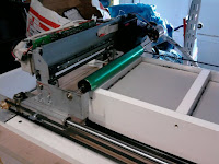
  Anyway, about this time I found a pair of 13mm precision shafts with 1 bearing block. Even though they were a few inches shorter than I wanted, the price was right (free) so I scrapped the drawer slides and upgraded to the shafts. I figure the added precision can only be a bonus and the bearings were soooo smooth. I did have to buy some more linear bearings, but I made my own bearing block from hardwood (Poplar I think). I bolted the printer to the blocks and attached the rails to a sheet of MDF which will become the top of my printer. (I forgot to take a picture at this point but you can get the idea from this one)
Friday, August 28, 2009
How is this going to work?
Before I get too much farther I guess I should discuss how I intend to make this work.
Let me start by listing my liabilities;
Let me start by listing my liabilities;
- I don't have the first clue how to program a pic.
- Python might as well be a really big snake.
- Scripting is something i do to make my handwriting look nice on Christmas cards.
- Everything I know about electronics I learned from the Radio Shack " Getting Started in Electronics" book.
OK , now that that's out of the way, this is the plan.
- I will use software obtained elsewhere to "slice" my .stl file into images that will be sent from my laptop to the printer. ( more on this later)
- I will use the inkjet's firmware to handle the printing and the motion of the gantry (formerly the paper feed, now the x axis) during the printing phase
- Another PC (a worthless old PIII running TurboCNC in DOS) will control all other actions via g-code, steppers, optical sensors, switches, and a tanlge of wires. (don't worry I'll have more details when the time is right)
That's the basic idea anyway, The best part is that I didn't need to learn a whole new skill set. I was already familiar with TurboCNC, available here http://www.dakeng.com/turbo.html , and G code is no more difficult than old school BASIC (I think I just gave away my age).
One important note about TurboCNC. It allows the use of a PLC handshake (both input and output) that is vital. I didn't see the same command listed among the codes in Mach3. Be sure that whatever program you chose has the ability to pause and wait for a handshake. The importance of this will become clear when I explain the control sequence later. Oh yea, It also runs in DOS so you can use that old dusty computer you never got around to throwing away, and best of all It's Shareware.
The powder spreader
 The next logical step might have been to mount what remained of the inkjet on some rails or slides.... But instead I decided to jump ahead and mount the roller for the powder spreader (I figured it would be much easier to do while I could still move the inkjet around) even though I would not be able to test it until much later. The idea here is that a spinning roller pushes powder in front of it while leaving behind a very thin smooth layer. The roller is scavenged from an empty HP laser printer toner cartridge. The shaft, bushings, and dc motor I scarfed from some discarded office equipment. The gears I had left over from another project. This is where being a scavenger/pack rat really pays off. I fabricated one mount from a scrap of Plexiglas and the other is a piece of metal from my " Big box o' bits". I decided that the roller should be placed higher than the paper so it wouldn't drag across the just printed layer. It also had to be low
 er than the print heads so they would clear the edge of the build bin. And lastly it had to be level (easier said than done). I bolted my mounts to the sides of the inkjet and mounted the roller and motor. I now had my completed carriage assembly. As it turns out I had to tweak the roller assembly later when I got to the powder trials... but I'm getting ahead of myself.
Thursday, August 27, 2009
The donor printer
 The first thing to do is strip down the inkjet to the bare essentials. You should probably start by removing the covers and observing how it works. Print a few pages and see how the paper sensor works. On my lexmark there is a little plastic lever that is lifted by the paper as it is fed into the printer. This lever moves a plastic flag which is blocking an optical sensor on the circuit board. The sensor is blocked when there is no paper/ unblocked when paper is present. Once you have figured out how it works, you need to remove anything that is under where the paper would be. This includes any paper feed rollers, guides, or housing/framework. Don't forget to measure the distance between the print head
  and the paper (I did!). The paper feed motor on my printer is a stepper motor (On HP printers it is a dc motor with an encoder). I separated the motor and gearbox so they could be relocated to a stationary location. Some people remove the pcb so it can also be relocated. The the idea is to lighten the carriage but I decided it would be too much hassle to extend the ribbon cables to the print heads so I left it where it was. What I was left with was a carriage that I could mount on some linear slides so that instead of feeding a piece of paper under the print head, the printer would move over a bin of the build medium.
 Getting started
I will be building a 3d printer around an old Lexmark Colorjet printer that I had collecting dust in my closet. The basic idea is to build a 3d object by "printing" a series of slices onto a medium. After each slice is printed, annother layer of the medium is added on top of the previous one and the next slice is printed. In this way the object is created slice by slice from the bottom up.
Here is a basic list of what is needed:
- an old inkjet (my lexmark 5700)
- some linear slides (the higher quality the better, but you can start with drawer slides)
- 3 stepper motors (make sure they are strong enough for the job)
- 3 axis driver board (Xylotex, Gecco, Stepmaster, or similar)
- a power supply of the appropriate amperage
- an assortment of switches, optical-interrupters, relays, wire...
- some timing belts, pulleys, lead scews and nuts
- a variety of construction supplies (lumber, corner braces, screws, epoxy, wood glue, aluminum angle...)
- an old pc (I'm sure you have an old Pentium II or III collecting dust next to that old inkjet)
- software to make it all work
I'm sure I left a bunch of stuff out but I'll go into more detail with each step.
There are, as they say, "Many ways to skin a cat" (apologies to cat lovers). So my solutions are just one of many possible. Please feel free to improve on my humble tinkering.
Hello!
Where to begin...
This past Spring I attended the Wonderfest model and toy show here in Louisville. (Awesome show if you're into model building/ toy collecting) Anyway, one of the seminars was dedicated to rapid prototyping. After about 10 minutes I was like "This is so cool! I must have it!". Unfortunately I didn't have $15 G's burning a hole in my pocket. What I did have however was a basic mechanical and electrical aptitude and a new obsession. Oh yes... It will be mine!!!(insert evil scientist laugh here)
A few hours research on the web convinced me that I not only could do it but I already had much of what I needed for the project . I'm already well on the way to having a working 3D printer but I'll start at the beginning and chronicle my successes (and failures) and hopefully inspire others along the way.
If you are interested in building a 3D printer or just curious, be sure to check http://tech.groups.yahoo.com/group/diy_3d_printing_and_fabrication/
I also want to thank A. Fogassa for his help and inspiration. Check out his blog at http://homemade3dprinter.blogspot.com/
Subscribe to:
Posts (Atom)
