I can't believe the Summer is over and winter is just around the corner. If you haven't already guessed, I have way too many interests and find myself too easilly distracted by the project of the moment. The good news is that now that the weather is turning nasty and it gets dark early, I'll be working on indoor distractions (like the 3D printer).
I'm going to try and force myself to stay focused and actually finish this project before I flit off to the next one. I have been thinking on some changes to the Z axis design. I would like to be able to buy a precision linear stage but the cost is prohibitive. I'm pretty certain I can build something that will be "good enough" but I'm still working out the details. There are a few other changes I want to make to my original design concept. That often happens when my concepts meet the reality of fabrication.
Once I work out the Z axis It shouldn't take too long to assemble. I hope to have a prototype ready for testing by the end of the year.
Thanks for checking back, I'm sorry for staying away for so long.
Friday, October 28, 2011
Sunday, July 17, 2011
Now with Real Tilting Action!
 I've been working on the resin tray. I needed a way to be able to test different coatings/coverings for the glass at the bottom of the tray. To that end I have made a frame that will hold the glass. I can prepare glass pieces with different coatings and change them easily. I do feel that I cheated a bit as I used my CNC to make the frame. I probably could have made it with my table saw and router table but the CNC was faster and much neater.
The tray will slide into a holder that floats on springs. It can be leveled by adjusting the bolts at the corners. The holders were made with much more mundane tools. A hacksaw for the aluminum and a table saw to cut the HDPE blocks. A drill press was used for the holes. What you don't see is the threaded inserts I found at the hardware store. They screw into the MDF and the bolts are threaded into them. The blocks slide up and down nicely on the bolts (I found some that had the top 2/3 unthreaded) but I foun
 d that I needed to open up the holes on the underside of the blocks so the bolts could "wiggle" a bit . Otherwise they would bind up when only one side was pressed down.
Here you see the finished assembly with a stepper motor to provide the tilting action. There is a eccentric (off center) wheel that presses down on a lip on the back side of the tray. The tray will be tipped between layer exposures to help separate the cured resin from the vat floor. Then the Z axis gets raised slightly before the next slice is exposed. I may need to relocate the stepper so it won't interfere with the Z axis.
Sunday, June 12, 2011
Baby steps
 I have started the modifications to turn my CNC router into a test bed for my 3d printer design.
I added a platform to the Z axis that will hold the build platform. The resin tray will hang off the edge of the table so I can have the projection from below. For now I just have a piece of Plexiglas as a placeholder for the tray.
Watch the video to see it in action!
What you see is Mach3 running a macro. The macro opens a PowerPoint slide show. Then lowers the z axis quickly to the top of the tray then slowly to the bottom so it doesn't splash down into the resin. The macro then shows a slide for the set exposure time alternating with a blank(black) slide while the z axis repositions itself for the next layer. Then the next slide is shown . Lather, rinse, repeat.... When the last slide is done the z axis is raised to its full height so the build tray can be slid out of the holder. The images you see on the screen will be projected up from below the Plexiglas. Of course all the timings will need to be adjusted once I start testing with actual resin.
What you see is Mach3 running a macro. The macro opens a PowerPoint slide show. Then lowers the z axis quickly to the top of the tray then slowly to the bottom so it doesn't splash down into the resin. The macro then shows a slide for the set exposure time alternating with a blank(black) slide while the z axis repositions itself for the next layer. Then the next slide is shown . Lather, rinse, repeat.... When the last slide is done the z axis is raised to its full height so the build tray can be slid out of the holder. The images you see on the screen will be projected up from below the Plexiglas. Of course all the timings will need to be adjusted once I start testing with actual resin.
Next up... I'll add the projector. I just need to get a VGA splitter and a front surface mirror.
Sunday, June 5, 2011
Details, Details
I've been doing a lot of brainstorming with a kindred spirit (Jon) I met over at the Chemshapes.com forum (formerly Snygro).
My ultimate goal here is to come up with a 3d printer that can be built cheaply from easily obtainable materials without access to a full machine shop. That being said, I need a practical test bed to try some ideas. To that end I am going to make modifications to my diy cnc router and add 3d printing capability to it. The router already has a functional z axis and all the electronics. This way I can work out the design details and transfer that to my dedicated desktop printer design.
On the software, I had planned on using MS PowerPoint to create a slide show of my layer slices but was having a very difficult time figuring out how to time each slide with a blank(black) transition that was long enough. It could be done with custom animations but not to all the slides simultaneously. If there were hundreds or thousands of slides that would really suck! I couldn't find a slide show program that would let me set the dark time between slides so I was trying to learn Visual Basic so I could write one for myself. The problem is I was having trouble wrapping my brain around it and was getting frustrated when I couldn't get it to do what I wanted.
In rides Jon Watson to the rescue.
He solved two problems in one stroke.
1. I needed to create a slide show with the appropriate timings and 2. then coordinate that show with the motion control of the printer. At first I was thinking of having some sensor on the printer that "looked" for when a blank slide was displayed so it knew when to make its moves.
Jon came up with a macro to apply the animations to all the slides automatically and then use Mach3 to call up the slides and coordinate them with the motion control software. Anyone with a background in CNC knows about Mach3 but for the rest of you, It's a program that uses something called g-code to control a CNC machine. I own a copy but wasn't planning on using it for this project because it is a significant investment (for a hobbyist) and I wanted to keep the final build cost as low as possible. The really cool thing about Jon's solution is that he uses Mach3's scripting ability (something I hadn't even looked at) to do all the work. That means that the trial version which has a limit of 500 lines of code will work because the script doesn't actually need to run any g-code. Mach uses Cypress Enable a much more (I think) intuitive scripting. After studying Jon's script and going over the Cypress manual I was able to make a few tweaks and removed the need (I hope) for the custom animations in PowerPoint. Now you just place a blank slide as slide #1 and Mach3 will alternate the blank slide with the slice slides. Of course I still need to set the exposure and delay times. That can only be determined once the test bed is up and running and I have some resin to test.
I'll post all the code when I'm sure it isn't buggy.
Sunday, May 22, 2011
Size Does Matter!
I started working out the dimensions and realized that first I needed to know the focal distance of the projector. After playing with the projector I'm planning on using I quickly realized a few things. Projectors are made to project LARGE and not straight ahead. They can also put out some serious heat. The projector I have has a minimum focal distance of 50 inches and throws a picture 32 inches wide. Not ideal for what I have in mind. However, I don't want to make any drastic/permanent alterations to the optics because I would like to be able to still use it for movies. While I was pondering my options I remembered a set of macro lenses I bought for my K-1000 some 20 years ago. (Does anybody else remember when cameras actually used film?) I played with the lenses and found that by placing them directly in front of the projector lens I could drastically shorten the throw distance (and image size). By using the +4 lens the distance was reduced to about 7 inches from the front of the projector and the image size could be adjusted with the zoom to 6 inches wide. The best part is that I don't have to alter the projector in any way. I'll get a filter adapter and rig up something removable to hold it in place. I'm also going to have to be careful not to block the cooling vents in the front. If I was going to place the projector vertically under the resin tray it would be blasting hot air right at it and would get the resin quite warm in no time. I will avoid that by placing the projector behind and horizontally but may have to use a supplemental fan to move all that heat away from the projector.
 movies. While I was pondering my options I remembered a set of macro lenses I bought for my K-1000 some 20 years ago. (Does anybody else remember when cameras actually used film?) I played with the lenses and found that by placing them directly in front of the projector lens I could drastically shorten the throw distance (and image size). By using the +4 lens the distance was reduced to about 7 inches from the front of the projector and the image size could be adjusted with the zoom to 6 inches wide. The best part is that I don't have to alter the projector in any way. I'll get a filter adapter and rig up something removable to hold it in place. I'm also going to have to be careful not to block the cooling vents in the front. If I was going to place the projector vertically under the resin tray it would be blasting hot air right at it and would get the resin quite warm in no time. I will avoid that by placing the projector behind and horizontally but may have to use a supplemental fan to move all that heat away from the projector.
Tuesday, May 17, 2011
It's mocking me!
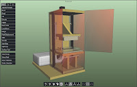 I've mocked up a quick 3d of my design concept. As I said before, I'm going to use easily obtainable budget priced components whenever possible. I plan to use MDF which I will seal with paint, glass, Plexiglas, aluminum and steel angle. I can get most of the construction materials from Home Depot or a local plastic supplier. I'll break down the materials as I build. I've started collecting what I'll need so I can begin building soon.
 Until then here are some more screen shots of the design. This was just a quick mock up so the sizes are approximate. I'll work out the exact dimensions as I build.
Here we go again
 Here is a quick sketch of the basic idea. As you can see it's a little different from the previously mentioned lesson plan. In the example in the lesson plan the image is projected on the surface of a tank (in that case a beaker) of resin and the part is submerged into the resin as it is solidified. A variation of this method is to expose the resin at the bottom of the tank to the UV and have it stick to a plate which is raised up out of the resin. Each new layer sticks to the previous one and is lifted upward. I chose a bottom up method because then I don't need a resin tank deep enough to contain my maximum z travel. Also the submersion tank method requires a large volume of resin from the start. A shallow tray only requires a small volume of resin be maintained (and possibly exposed to the degrading effects of unwanted UV and moisture). Also the Z build height will not be limited (theoretically) by a fixed tank depth or my financial ability to fill said tank. Most of the designs I have found in my research place the projector vertically directly under the resin tank. I am going to place the projector horizontally behind the z axis. Initially I plan to borrow a projector as I see this as being the single most expensive component. By placing it behind I can easily remove/replace the projector and also have much more flexibility over the focal distance. This also will keep the total height of the printer smaller. If I went all vertical the total height would probably end up close to 4 feet. Lastly, since the projector won't be mine (at least initially) I really want to protect it from any resin drips!
I'm going to try and keep this as simple (basic) as possible. I envision a build plate that is in a carrier so it can easily be removed when the print is done. Also the resin tank needs to be removable for easy cleaning. Then there is the matter of preventing the cured resin from sticking to the bottom of the tank. I think some combination of non stick surface and mechanical movement. As you can see it will be easy to get very complex. I'll have to resist the temptation to over engineer. I'm working on a more detailed design mock up that I'll have ready in a few days.
My goal is to create a 3D printer that can be built with readily available, easily fabricated and affordable components.
I hear you thinking..."He must be MAD! It just can't be done!"
Only time will tell.... Cue the manical laughter.
Monday, May 16, 2011
It's a Brand New Day....
OK, I've been kicking around some ideas. The basic idea is presented here.
https://www.nano-cemms.illinois.edu/media/content/teaching_mats/online/3d_printing/docs/guide.pdf
As you can see it's really not that complicated (mechanically at least). For this project I'm going to try to stick with 2 principles. Keep it simple and make it cheap! My intention is to build a functional 3d printer within my almost non-existent budget. Later, if successful and as finances allow, I can upgrade components to achieve higher precision.
I can break this project down into 3 parts:
1. Hardware
2. Software
3. Chemistry
I'm confident that I can build the hardware portion of the printer. It's actually much less complex than the inkjet/powder printer. In fact, I'm going to harvest much of what I need from that progect. I'm working on a design sketch which i'll post soon.
The software... well, I would love to be able to purchase comercial RP software (Magics 15) but there is no way that will ever happen. I think it's considered the gold standard because you need a pile of gold to buy it! It seems that any software that does everything I'll need (including generating support structures) falls into the catagory of "If you have to ask you can't afford it". Since I don't have access to a pile of gold, I'm going to make due with what I can afford (free) and what I already have (Powerpoint). I'll have to make due with manually adding support structures. I'm really hoping that the open source community will develop something for that.
Lastly, the chemistry. I'll worry about that after I get the hardware working. I see this as being alot like the ink/toner of 2d printers. The real money is in the consumables.
Now to sketch up some designs and start collecting materials.
Thursday, May 5, 2011
Stick a fork in it!
As you can probably guess by the title of this post I have officially given up on the powder based printer concept. I never could get the lexmark cartridges to work quite right. I couldn't get them to work well after they were refilled and the plaster dust kept clogging the nozzles of the brand new ones. Perhaps if I had started with a better donor printer. I seem to remember there was a reason I put the lexmark inkjet in the closet in the first place and that reason was that the cartridges sucked. Oh well...
While I'm done with the powder based concept I have not lost my interest in developing an affordable 3d printer. And when I say affordable I mean one that I can afford (Meaning as cheep as possible). I'm really excited by some of the work being done on DLP 3d printers and have decided to shift directions and pursue this technology.
Check out what Junior Veloso is doing with his DLP printer!
http://3dhomemade.blogspot.com/
If that doesn't get you fired up then youre reading the wrong blog!
There's also an open source project by TJ Snyman that's in the development stage
http://tjsnyman.com/tjsnymanblogspot/?page_id=531
The good news is that I can cannibalize the powder printer for the electronics and mechanical stuff. Now to start gathering materials and start planning.
Subscribe to:
Posts (Atom)
