I can't believe October came and went so quickly! (It's way too easy to get sidetracked.) Anyway, I just received some new Dental plaster and some additives to try out so now I have no more excuses. Time to roll up my sleeves and start testing. Hopefully it won't take a month this time to show some progress.
Thanks for being patient.
Thursday, November 5, 2009

Sunday, October 4, 2009
I could use a thousand words or.....
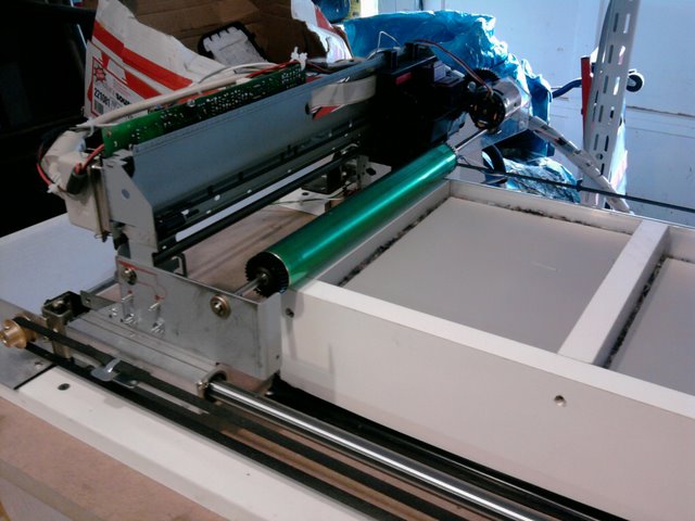
 I was asked to describe how the various components interact. Instead of a lengthy (and confusing) description I offer these diagrams and a (hopefully) shorter description. The first step to building a 3DP is to modify the inkjet into a flatbed printer. To that end you need to have a way to move the entire printer over the paper instead of the paper under the printer. There are 2 problems with moving the printer body directly with the original paper feed motor. First, it probably isn't strong enough and second it will probably make unwanted movements as the printer tries to ready a new piece of paper. My solution was to place a homemade encoder on the paper feed motor that would supply "step" pulses to a second more powerful stepper motor. In this way I could easily interrupt the pulses and stop the gantry movement even if the paper feed motor was still moving. Another source of pulses can be used to return the gantry to the starting position. Switches 1 and 3 are "safety" limit switches to prevent over travel of the gantry. Switch 2 swaps the source of the pulses and changes the printer from "print" to "reset". Also, you will need some way to tell the printer when the "paper" is present and "out". Usually there is an optical sensor which you can block/unblock at the appropriate times. This setup works if you are printing only one page at a time and don't mind resetting it manually each page. Of course, you could design a circuit to automate the switching process and replace switch 2 with a relay.
To make a 3DP I needed to not only automate the "reset" but also, precisely control the movement of 2 bins, switch a dc motor on an off, and be able to tell the printing computer to "wait" and not send the next page until the printer is ready. I could have built a dedicated circuit to do all this but as I stated earlier, My knowledge of electronics is limited and I don't have a clue how to program a PIC. I decided instead to go with a CNC setup. The inkjet still does all the actual printing then the CNC takes over and re setts the gantry, adjusts the powder bins,spreads the powder, and then tells the printing computer that it can send the next page. You can see in the diagram that PC 2 has replaced the pulse generator and a relay has replaced switch 2. Additionally, 2 more steppers and a 2 axis stepper driver have been added. Switch 4 gives feedback to the control program and signals the change from the print to the recharge cycle. Relay 2 breaks the connection on pin #11 of the inkjet's parallel port. this tells the PC that the printer is "busy" so it wont send another page until the printer is ready. Relay 3 is connected to the motor that runs the powder roller. The breakout board is a convenient place to make all the connections to the parallel cable and PC 2. Note that the parallel port of the PC doesn't output enough current to drive a relay directly so I used the outputs to switch transistors that supply 5v to the relays.
For the CNC control I use TurboCNC and a G-code program. The program is a step by step set of instructions which can be used to set the logic state (high/low) of the parallel port pins. Also, pins can be monitored and step pulses can be sent to the stepper drivers.
Hopefully this helps clarify what I've done. If I haven't answered your questions feel free to ask.
Wednesday, September 23, 2009
Time to get back to it.
Well, I’ve allowed myself to be distracted the last few weeks but now it’s time to get back to it. Now I’m at the testing phase and my motivation has waned terribly. I guess I was not looking forward to repetitive tests to find the best powder/ink formulations. But, now it’s time to get off my lazy butt and, as the old Nike ad once said, “Just do it”. Anyway, in an effort to self-motivate I’ve been creating a CAD model for the first project to be printed. Now I just need to finish the testing so I can get to it.
 Here is a shot of the project I mentioned. It’s a tabletop holder for one of those LED tea lights. The top and bottom halves are separate. Total height is about 7 inches (18 cm). Each piece will be approximately 900 layers! I reeeeeally need to make sure the printer is working flawlessly before I attempt it.
When I mention this project to my friends, most are like “That sounds really cool, but what are you going to do with it?” The answer depends a lot on the properties of the “printed” plaster. The level of detail and the hardness of the “prints” will determine what I can (or can't) do with them. What I hope to be able to do is model on the computer then “print” parts which can be used as masters to make molds for urethane casting. Well, that’s the goal anyway. I’ll have to see what it can do and modify my expectation accordingly.
 Here is a shot of the project I mentioned. It’s a tabletop holder for one of those LED tea lights. The top and bottom halves are separate. Total height is about 7 inches (18 cm). Each piece will be approximately 900 layers! I reeeeeally need to make sure the printer is working flawlessly before I attempt it.
For now, I’ll busy myself with some small geometric shapes as I test/tweak the equipment. Of course I’ll let you know how it goes.
Wednesday, September 9, 2009
“It cuts though a tin can then slices a tomato!”
While I’m waiting to make repairs/ improvements to the belts, I thought I might take a moment to talk about slicing stl files. I did some Google searches and found several software packages that could slice my files but they were way out of my price range. I guess if I was going into business as a rapid prototyper I could rationalize the expense, but for my own personal/hobby use the prices were prohibitive. There were some budget (free) options (like slicing with PovRay) but I couldn't get them to work and didn’t understand the scripting involved. Then I found the Project 1 utility at the Yahoo DIY 3D Printing and Fabrication group. Thank you Paulo, for graciously making your slicer available to the groups’ members.
The utility is easy to use and doesn’t require any additional programming skills. Simply open your stl file in the slicer, pick a printer, set the slice thickness, and hit print. You can scale and rotate the model as well as shift the print position to center it on the page. One thing to note is that the measurements are in metric. You need to convert your stl to millimeters if you want it to print at the size you are expecting. My other observation is that the mesh must be clean and watertight. From what I understand, that’s not unusual for 3D printing. It’s probably also the reason the other software was so expensive. Unfortunately, my meshes are typically neither clean nor watertight (I really need to learn better 3D modeling skills).
I am modeling in Silo and using MeshLab to check and repair my meshes. Some are so hopelessly messed up that I’ll have to go back and start over. (There is also a slice feature in MeshLab but it outputs svg outlines and I need silhouettes.) MeshLab is open source and can be found at Sourceforge (http://sourceforge.net/projects/meshlab/). Silo is available from Nevercenter (http://www.nevercenter.com/about/) for a modest $99 ($159 for the pro version). They have a 30 day trial if you want to check it out and a very friendly and helpful users community. I'm still very much a Noob with Silo but I found it to be much more intuitive than Blender and WAY less expensive than Rhino, Lightwave, or any of the CAD packages (Hell, even Google Sketch Up is like $495 if you want to be able to output anything other than their own format). Again, if this wasn't a hobby (and I wasn't incorrigibly cheap), expese wouldn't be such a big issue.
Anyway, now I need to make my repairs and whip up some test files.
The utility is easy to use and doesn’t require any additional programming skills. Simply open your stl file in the slicer, pick a printer, set the slice thickness, and hit print. You can scale and rotate the model as well as shift the print position to center it on the page. One thing to note is that the measurements are in metric. You need to convert your stl to millimeters if you want it to print at the size you are expecting. My other observation is that the mesh must be clean and watertight. From what I understand, that’s not unusual for 3D printing. It’s probably also the reason the other software was so expensive. Unfortunately, my meshes are typically neither clean nor watertight (I really need to learn better 3D modeling skills).
I am modeling in Silo and using MeshLab to check and repair my meshes. Some are so hopelessly messed up that I’ll have to go back and start over. (There is also a slice feature in MeshLab but it outputs svg outlines and I need silhouettes.) MeshLab is open source and can be found at Sourceforge (http://sourceforge.net/projects/meshlab/). Silo is available from Nevercenter (http://www.nevercenter.com/about/) for a modest $99 ($159 for the pro version). They have a 30 day trial if you want to check it out and a very friendly and helpful users community. I'm still very much a Noob with Silo but I found it to be much more intuitive than Blender and WAY less expensive than Rhino, Lightwave, or any of the CAD packages (Hell, even Google Sketch Up is like $495 if you want to be able to output anything other than their own format). Again, if this wasn't a hobby (and I wasn't incorrigibly cheap), expese wouldn't be such a big issue.
Anyway, now I need to make my repairs and whip up some test files.
Monday, September 7, 2009
Lather, Rinse, Repeat
 Well I filled it with powder and took it for a test drive. The first thing I noticed was that I needed to add something to keep the powder from spilling over the sides of the bins as it was being rolled out. I'm still tinkering with the roller speed trying to get the smoothest layer possible. (I think the problem may be partly with my plaster formula) Anyway it was good enough to run some tests.
The print and recharge cycles run great. (Sorry for the really awful video) I am using Paulo Cesar's Project 1 (available at the Yahoo DIY 3D Printing and Fabrication group) to slice my stl files. Many thanks to Paulo for a slicer utility that is easy to use and doesn't require me to know how to script or program.
Oh Noooo!!!!! Somewhere around layer 170 one of the belts came loose! I'm going to have to come up with a more secure clamp. Once I get the belts fixed I'll be ready to try again. For now I'm trying to use up the ink in a new cartridge. I tried to refill an old one with the water/vodka mix but it was hopelessly clogged. I figure I'll have better luck with a new one. For now I'll keep working on getting the powder layer as smooth as possible. I also need to install a limit switch on the supply bin so it stops when it reaches the top.
Thursday, September 3, 2009
Some Assembly Required
Putting it all together:



I had an old cabinet (scavenged of course from an office renovation), that makes the perfect home for my new printer. I screwed the MDF board, with the rails and inkjet, to the top of the cabinet and attached all the electrical bits to the side (I'll move them inside once I'm satisfied it all works). I carefully cut a hole in the MDF under the printer and lowered the bins into place. I used shims to level it at the right height before I screwed it to the inside of the cabinet. I also used some angle braces to support the bottom edge of the bins. I next installed the steppers and lead screws. Luckily there was just enough room between the screws for the PC. I also rigged up a plastic storage container to catch the powder overflow. I mounted the keyboard in the space where a drawer once was. Lastly, I put a shelf above the printer so I would have someplace to put the monitor, my laptop and the mouse. If I were to put the plastic covers back on the inkjet it might even look semi-professional.


Welcome to The Pit of Despair!
 As I mentioned earlier, my build chamber will be 8 ½ x 11 x 10 inches. The supply bin will be half that size. There will also be a small chute (henceforth known as “The Pit of Despair”) so excess powder can be collected . I chose to construct the bins out of some 12 inch wide melamine shelving which I salvaged. I hate cutting large pieces on the table saw and these were already the right width. I only had to cut them to length which made it much easier to keep them “square”. Also, they don't need painting or sealing. I had a problem with the clearance on one side of the printer. The printing area started about ¼ inch from the cartridge cleaning/parking station. I solved this by topping that side with a piece of aluminum angle.
 For the platforms I used more of the melamine shelving. I edged the platforms with felt weatherstrip. This seems to slide nicely on the melamine and should give me a good enough seal. I might have some leakage at the corners but if it's a problem I can always remove the platform and vacuum it out. I used roller skate bearings on the build platform and where the poles exit the bins. I used Teflon sliders on the supply bin because they were cheap and I don't need the same precision on the supply side. The pole is a piece of galvanized conduit which I attached with some pipe fittings and set screws.
 The lead screws and nuts I removed from automotive jacks. I figured if they could lift a car they would be more than sturdy enough. A trip to the junkyard netted me 2 jacks for $5. What a deal! (It did take me a couple hours with a hacksaw to remove the screws and nuts so maybe it wasn't that great a deal) A while back I picked up 2 surplus steppers with gearboxes from www.allelectronics.com. They were like $15 each and I couldn't pass them up. I'm glad I didn't because they are perfect for this project. The gear ratio is 18:1 so there is plenty of torque to lift the heavy bins full of plaster. It took a little Macgyvering to attach the screws to the gearboxes.
Now that the bins are complete, they need to be installed under the printer.
Subscribe to:
Posts (Atom)


